Flight Simulator Controller
Microsoft Flight Simulator 2020 sets the bar for home flight simulator software and the Honeycomb Alpha yoke does the same for home simulator yokes, but no throttle or trim controller for small aircraft stands above the rest. After flying with the Alpha yoke and a keyboard for a few days I decided I needed a throttle and trim controller that matched the quality of MSFS and the Alpha. I was disappointed with what the market had to offer so I set out to build my own.

Requirements
I wanted a throttle and trim controller that would supplement my Honeycomb Alpha yoke. I wanted it to feel familiar to student pilots who most often learn to fly in Cessna 172 and 152 aircraft. Personally, I'm on the fence about taking lessons myself and part of my reason for having a home flight simulator is to gauge my interest in whether or not I want to call up my local instructor to schedule lessons.
The requirements I set for this project,
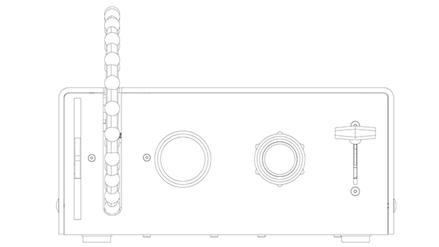
- Realistic trim wheel
- Realistic throttle and mixture knobs
- Realistic flaps lever
- USB-C connectivity
- Aesthetic that compliments the Honeycomb Alpha and my desk in general
- Microcontroller programmed with Circuit Python
Hardware
Being more comforatable with electronics than I am with hardware I decided to start with the physical design of the controller. If any part of this build were to fail it would have been the hardware. Initially, I thought that the entire controller might be 3D printed but soon stumbled across the laser cutting services of Send Cut Send. Seeing how easy their service makes laser cutting and CNC bending I decided to try it.
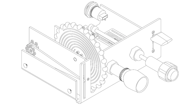
Enclosure
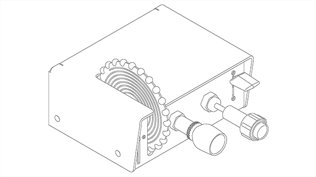
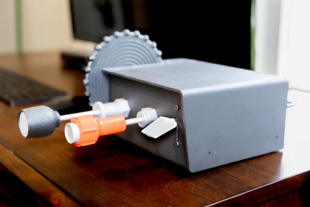
I chose to make the enclosure out of 1/8 inch aluminum which I knew would be easy to work with, affordable, and give the controller enough weight to not slide around my desk. To give the enclosure a touch of style, I included a lip around the front face that has the look and feel of a glareshield. That glareshield is part of the "top" which only contains the USB-C connector. All other components are contained in the "base" which makes adjustments and repairs possible simply by removing the top.
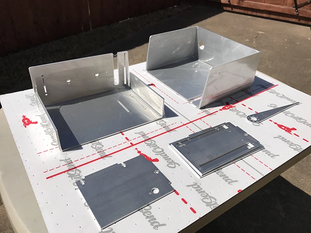
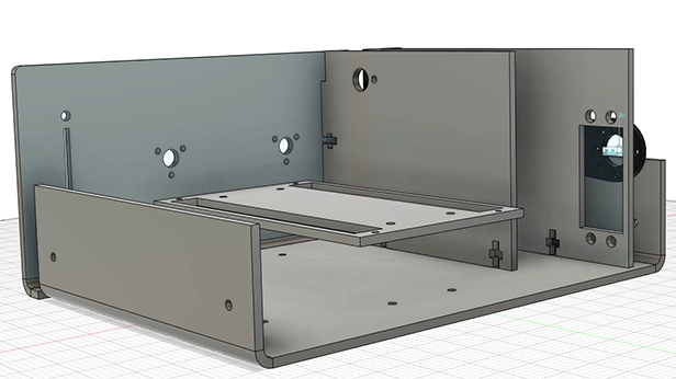
Inside the enclosure there are brackets and plates that mount electronic components. These pieces assemble with t-shaped slots and channels where nuts and bolts fix flat, perpendicular pieces to each other. The parts I received from Send Cut Send fit together surprisingly well. If I had this build to do over again I would design the parts with less clearance as the lasercut parts were spot on and needed very little wiggle room! The CNC bends were also far more precise than I expected them to be which made for nice, tight fitment. Thanks to the design guidlines that Send Cut Send offers on their website I was able to include relief cuts in the parts which I believe also contributed to how well the parts fit together.
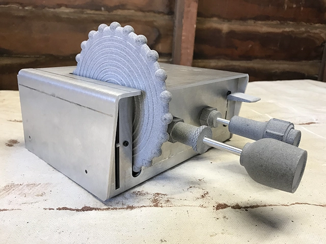
The tactile parts of this build were all 3D printed. Initially I wanted to use real parts from an aircraft salvage but could not believe how expensive salvaged parts are. This led me to model and 3D print those parts myself. Though I tried, I never found dimensioned drawings of a trim wheel or any of the knobs so I mined the web for photos instead and used ballpark estimates from a CFI buddy of mine to get the proportions close enough to feel representative of a real plane.
All the knobs were printed using a laser sintering technique. I chose this method when I had the parts printed because it was cheaper than other methods. Sintered parts have a slightly rough finish which gave the trim wheel and throttle knob a realstic bumpy texture. For realism, the mixture knob and flaps lever needed to have a nice smooth finish which required a couple rounds of sanding and priming, and careful attention to paint application. In the end those parts turned out quite nice as well. Because the parts are printed, the friciton nut on the throttle and the button on the mixture knob are purely for appearance. I would have preferred that they work but that was one feature I was willing to compromise on in order to simplify the build.
The trim wheel rotates about three revolutions before hitting its endstops and its position is encoded using a multiturn potentiometer. In order for the trim wheel to be set to its neutral position before each flight it needed a trim indicator. I considered using a pulley system that would link the trim wheel to a needle which would not have required any electronics but landed on driving a needle with a servo motor instead. This works really well and turned out to be easy to implement. The needle is another lasercut part and attaches to the servo mother with a splined hub from Pololu.com.
Electronics
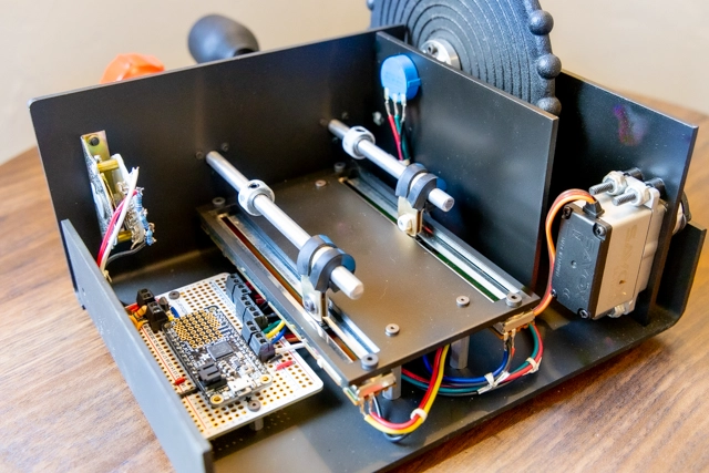
The part of this build that I'm most pleased with is the flaps lever. It needed to have four firm detents. Searching led me to guitar pickup selector switches. They can be purchased in a couple configurations and often do not come with knobs with makes attaching one of my own quite easy. When it arrived in the mail I knew it was perfect. It was the right size and the feel of its mechanism felt just like the detents of a real flaps lever. One question remained though and that was how to interface it with the microcontroller. Typically when switches drive microcontroller pins pull-up resistors are used and each switch position drives its own pin. One challenge I set for myself with this project was to optimize the microocontroller for the project. By that I did not want dozens of unused pins, or an obscenely overpowered board. That meant that I did not have enough pins available for each flap position to have its own. Instead I decided to build a resistor ladder where each switch position selected a different node in the ladder and connected that node to a single analog pin on the microcontroller. By reading the voltage applied to that pin it became possible to know the position of the switch. For simplicity, I soldered those resistors directly to the terminals of the switch.
Linear potentiometers were used to encode the position of the throttle and mixture knobs. I used epoxy to attach the knobs to 1/4 inch aluminum rods and those rods attach to the potentiometer wipers with p-clamps which are typically used for holding wires in place. Attaching the p-clamps to the potentiometer required drilling a hole in the wiper tab. To limit the range of motion of the knobs, I used adjustable collars inside the enclosure to give both a realistic feel.
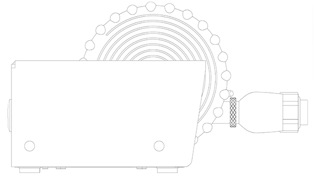
The trim wheel directly drives a multiturn rotary potentiometer. It rotates about three times endstop to endstop which is close to that of the trim wheel in a 172. The weakest part of this build is that potentiometer. It has a 1/4 inch shaft that directly attaches to the 7 inch trim wheel. The large diameter of the wheel means that turning the potentiometer requires very little effort. In fact it is so easy to turn, it can be difficult to feel the endstops of the potentiometer making it easy to over-rotate the potentiometer. Nothing seems to happen when it is over-rotated, but I wish it had a firm endstop. One way to prevent over-rotating the trim wheel is to pay attention to the trim indicator. The indicator is a long pointer with a white tip that is actuated by an RC servo motor. The micrcontroller reads in an analog voltage from the rotary potentiometer and maps that voltage to a PWM signal which drives the trim indicator servo. In the first iteration of the code, the servo motor was noisy. It chattered even when the trim wheel was not moving. To help with this I implemented a filter that heavily averages the potentiometer readings to ensure that the servo only moved when the trim wheel was moved an appreciable amount.
Code
The microcontroller used is an Adafruit Feather M0. It was selected for its ability to be programmed with Circuit Python -a Python flavor I've been wanting to try. Another reason for using Circuit Python on this project is that I did not want to have to spend too much time focused on the USB and Human Interface Device (HID) aspects of the code. I wanted to pass that off to well established functions allowing me to focus on the specific application at hand; interfacing with MSFS.
import board
import analogio
import digitalio
import time
import usb_hid
from adafruit_hid.gamepad import Gamepad
from adafruit_hid.keyboard import Keyboard
from adafruit_hid.keycode import Keycode
import pwmio

controller = Gamepad(usb_hid.devices)
kbd = Keyboard(usb_hid.devices)

flapLever = analogio.AnalogIn(board.A0)
throttleKnob = analogio.AnalogIn(board.A1)
mixtureKnob = analogio.AnalogIn(board.A3)
trimWheel = analogio.AnalogIn(board.A4)

servo_pwr = digitalio.DigitalInOut(board.D10)
servo_pwr.direction = digitalio.Direction.OUTPUT

def mapFromTo(x,a,b,c,d):
   y=(x-a)/(b-a)*(d-c)+c
   return y

def getFlaps():
    # Lazy debounce
    f = 0
    for i in range(1,100):
        f = f + flapLever.value
    f = int(round(mapFromTo(f/100,200,64900,127,-127),0))
    if f < -127:
        f = -127
    if f > 127:
        f = 127
    return f

def getThrottle():
    t = 0
    for i in range(1,100):
        t = t + throttleKnob.value
    t = int(round(mapFromTo(t/100,17600,64800,127,-127),0))
    if t < -127:
        t = -127
    if t > 127:
        t = 127
    return t

def getMixture():
    m = 0
    for i in range(1,100):
        m = m + mixtureKnob.value
    m = int(round(mapFromTo(m/100,21500,64800,127,-127),0))
    if m < -127:
        m = -127
    if m > 127:
        m = 127
    return m

def getTrim():
    tr = 0
    for i in range(1,100):
        tr = tr + trimWheel.value
    tr = int(round(mapFromTo(tr/100,0,65536,-127,127),0))
    if tr < -127:
        tr = -127
    if tr > 127:
        tr = 127
    return tr

# Servo signal is a variable duty cycle 50Hz squarewave that has a period between
# 950 and 2050 microseconds -endstop to endstop.
# 1.97 and 2.3 experimentally found to be good endstops
def servo_duty_cycle(pulse_ms, frequency=50):
    period_ms = 1.0 / frequency * 1000.0
    duty_cycle = int(pulse_ms / (period_ms / 65535.0))
    return duty_cycle

def updateTrimIndicator(tr):
    servo_pwr.value = True
    i = 2.3 - (round(mapFromTo(tr,-127,127,1.97,2.3),3)) + 1.97
    if i < 1.97:
        i = 1.97
    if i > 2.3:
        i = 2.3
    trimIndicator.duty_cycle = servo_duty_cycle(i)
    return i

flaps = 0
throttle = 0
mixture = 0
trim = 0

staleFlaps = 0
staleThrottle = 0
staleMixture = 0
staleTrim = 0

servo_on = 0

while True:

    flaps = getFlaps()
    if staleFlaps != flaps:
        staleFlaps = flaps
        controller.move_joysticks(r_z = flaps)

    throttle = getThrottle()
    if staleThrottle != throttle:
        staleThrottle = throttle
        controller.move_joysticks(y = throttle)

    mixture = getMixture()
    if staleMixture != mixture:
        staleMixture = mixture
        controller.move_joysticks(z = mixture)

    trim = getTrim()
    # Sometimes trim bounces around, set a threshold for when an update is triggered.
    # Trim should change by more than one count before an update is triggered.
    # This is an attempt to cut down on servo chatter
    if abs(staleTrim - trim) > 1:
        staleTrim = trim
        controller.move_joysticks(x = trim)
        #Initialize PWM output for the trimIndicator (on pin D12):
        trimIndicator = pwmio.PWMOut(board.D12, frequency=50)
        servo_on = time.monotonic()
        updateTrimIndicator(trim)
        time.sleep(.05)
        trimIndicator.deinit()

    # If longer than 1/2 second since trim was updated,
    # kill power to the trim indicator servo
    if time.monotonic() - servo_on > .5:
        servo_pwr.value = False
    # If time.monotonic() ever rolls over between updates, reset servo_on.
    # Never let difference be negative
    if time.monotonic() - servo_on < 0:
        servo_on = time.monotonic()

    print(flaps, throttle, mixture, trim)

    time.sleep(.1)